Electrical Connection
Power Supply
Control units require the supplied 12V/1A power supply.
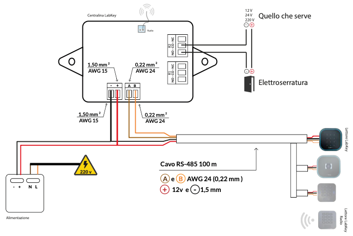
Every control device, except the LabKey Mini Radio Keypad, is powered directly by the control unit through the RS485 cable connection.
The radio keypad is the exception: it runs on a CR2450 battery that lasts an average of 2 years, depending on usage.
Relay Connection
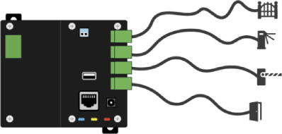
Connect the gate or electronic device you want to operate, break its circuit, and bridge it to the control unit’s terminal using one of the available relays.
Each control unit has 2, 4 or 8 relays, depending on the model:
- The 2-relay control unit can control up to 2 gates and connect up to 4 control devices.
- The 4-relay control unit can control up to 4 gates and connect up to 8 control devices.
- The 8-relay control unit manages 8 gates with 8 control devices.
Our contact is N/O (normally open) for the first 4 relays; on the 8-relay PRO control unit and the Light model, the relays can be either N/O (normally open) or N/C (normally closed).
All relays are rated MAX 10A/250V.
Light Control Unit Wiring
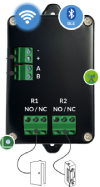
Connect the RS485 BUS to the + - A B terminal; using relays R1 and R2, close the circuit of the electronic device you want to operate. Follow the diagram below.
Download the wiring and dimensions PDF
Basic, PRO, LTE Control Unit Wiring
Connect the RS485 BUS to the + - A B terminal on all readers; using relays R1, R2, R3, R4, close the circuit of the electronic device you want to operate. Follow the diagram below.
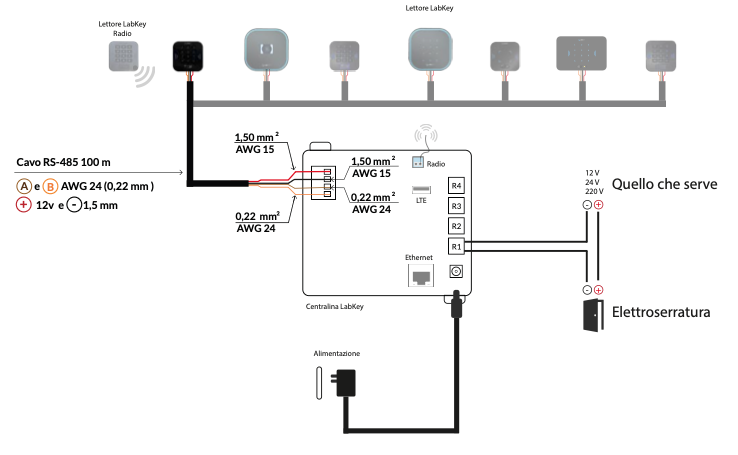
Download the wiring and dimensions PDF
ACCESS PRO 8 Wiring
For the PRO 8 version, we provide a 4.5A DIN-rail power supply, also rated at 12V, so that any additional gates can be wired directly as well.
Relays R1, R2, R3, R4 are N/O (normally open); relays R5, R6, R7 can also be configured as N/C (normally closed).
The BUS on the readers is wired in parallel and can be connected either in a daisy-chain or in a star topology.
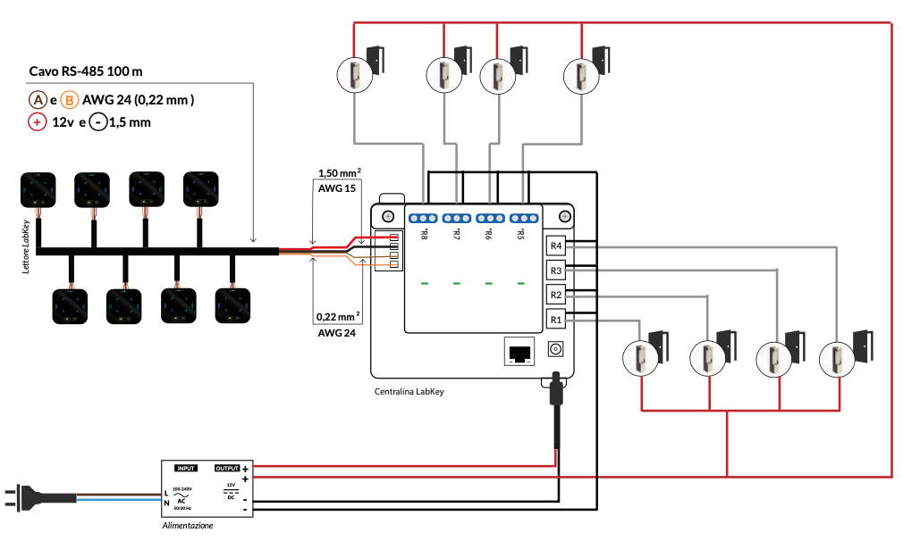
Download the wiring and dimensions PDF
GPIO Input Management
This is an additional hardware connector that can be requested on PRO control units. It allows you to manage 4 GPIO inputs and, in turn, control external devices or sensors.
The software supplied with these GPIO inputs lets you block access to a gate when the GPIO is in a specific state — for example, if the alarm is active, the reader denies access even to a user with correct credentials. It can also trigger devices when the GPIO reaches a specific state — for example, activating an alarm when the sensor detects a change of state.
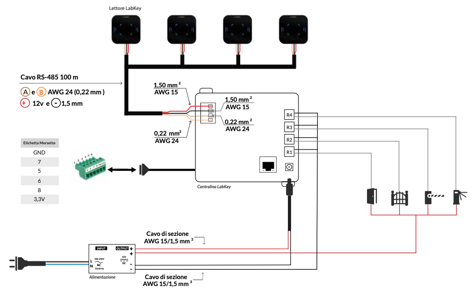
Presence Sensor Wiring
The Presence Sensor is a high-precision 24 GHz wireless accessory to pair with the GPIO input connector; it detects both moving people and people who are completely still — even someone asleep or motionless is still picked up — over a 120° angle and up to 3 meters away.
The sensor is powered through a dedicated 220V/12V power supply and connected to the control unit’s GPIO connector terminal; from there, the software can block a gate from opening when a presence is detected, trigger an alarm, or activate a scenario. Follow the diagram below for the connection.
UHF Antenna Wiring for Vehicle Access Control
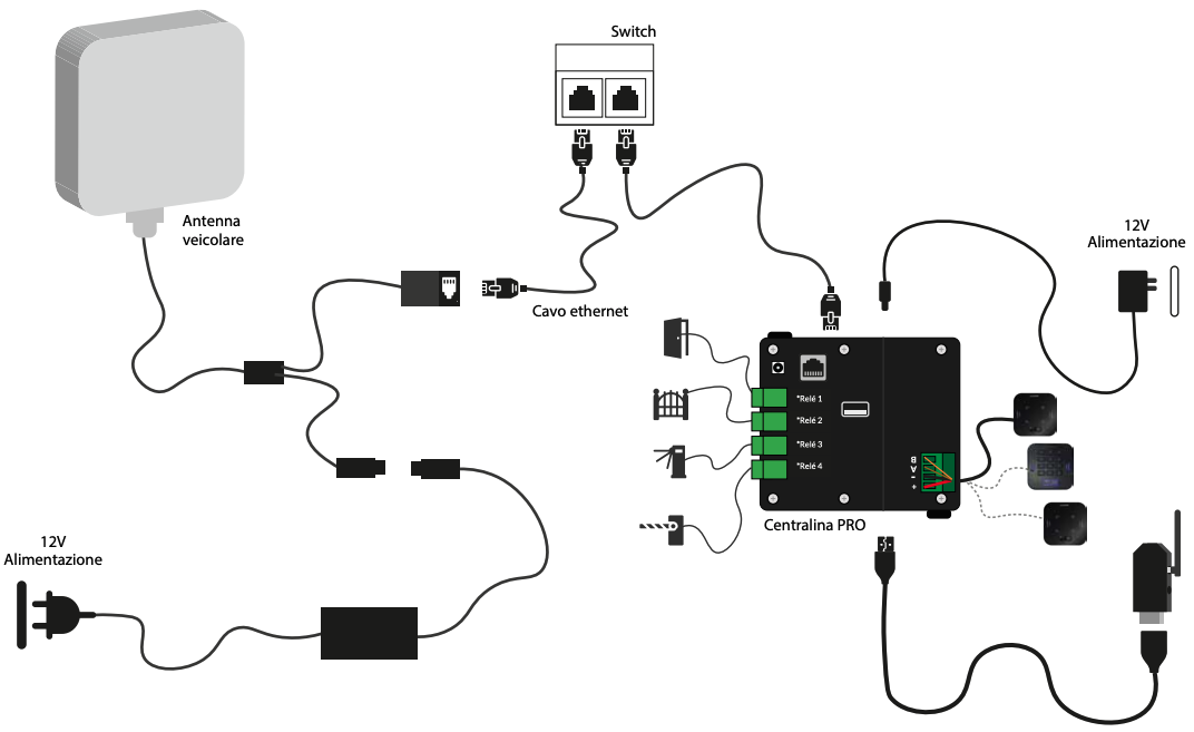
This accessory is available only for PRO control units; it automatically recognizes vehicles fitted with a UHF tag and opens the gate without any contact from the user.
The antenna communicates with the control unit via an external network switch, with its own separate power supply. Follow the diagram below for the connection.